Power on Reset – Capacitor calculations
Note : Written up for the Z80 processor, though same principal applies to others.
While power on instability is a less of an issue with modern processors, older, retro, MPU's definitely need reset on power up. Newer chip tend to have this build into the chip.
The issue is that the processor needs the power with in the chip and surrounding circuit to settle before it starts to operate. The surrounding peripherals, RAM/RAM, will also need time to settle.
If the processor has not settled, it will crash immediately, and you need to push the reset button, assuming you have one, to get the system running. RESET also resets the processor and sets the program counter to 0x00 where the Z80 starts execution from. The solution to this is very simple - You need to keep the MPU in Reset for a number of clock cycles. Then you can release the Reset and the processor will start to work.
The Z80 Manual states that it needs at least 3 full clock cycles of RESET at start-up.
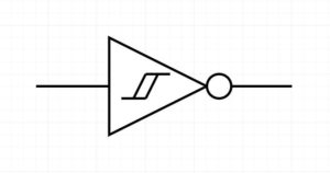
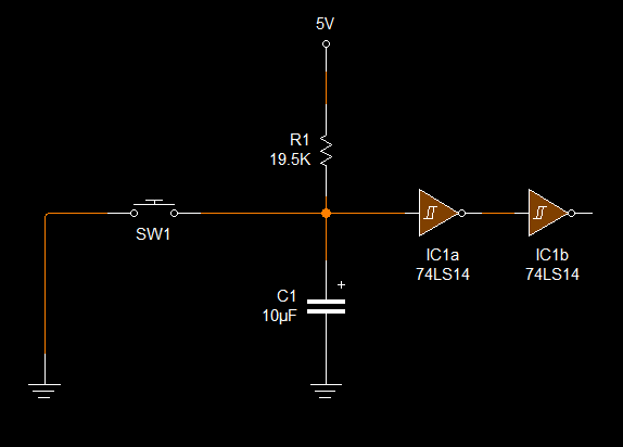
The circuit is a simple RC delay but there is an additional component that is required - A Schmitt trigger gate - usually an inverter. More on this in a moment. The RC circuit is designed to keep the Reset in a Low state (assuming ACTIVE LOW) for a small duration before pulling the Reset High. Visa versa for ACTIVE HIGH Reset.
This is also called a soft start.

Red - Voltage of the Reset Line
Blue - Voltage drop over resistor

When power is applied, the voltage on the Reset line will be 0 volts as 5v will be dropped over the resistor. As the capacitor starts to charge up, so the voltage of the Reset line will rise at a rate determined by the RC calculation and the voltage drop over the resistor will fall until the Reset line is 5V (which is the charged capacitor).
The RC calculation gives a Time Constant, which is a ratio of charge. In general the time taken to charge a capacitor (to 99%) is 5TC or 5 x the time constant.
time constant = resistance X capacitance.
The Z80 datasheet says "The Reset must be pulled low for a minimum of 3 full clock cycles."
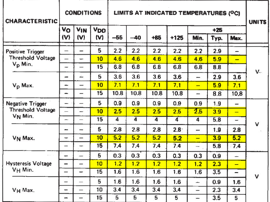
So how long do we need the delay to be? Well first we need to know the voltage the Z80 will consider 'High'. For that we need to look at the Z80 datasheet. According page 8 of the specification, the INPUT HIGH voltage is 2v. This kind of matches TTL logic levels which is between 2v and 2.7v.
So we need to keep the voltage below 2v for a least 3 clock cycles.
To know how long thee clock cycles are, we can calculate that. Assume the Z80 is running at 4Mhz. That will mean each clock period is 250ns.
The 3 clock cycles will be 250nS x 3 = 750nS. To be safe we can double that to 6 clock cycles which would then be 1.5uS (micro seconds).
In reality and especially with a homebrew PC or something where the start-up time is not critical, then the amount of time is really not that important as long as its over the 3 full clock cycles.
You can easily set a 100ms time just to be totally on the safe side.
The main thing to ensure is that the Reset line is kept below 2v for that duration. Lets work with a 100ms duration. Looking at the charge curve of a capacitor

As this is a 5v system, we cannot just use the RC5 calculation for the capacitor charge time. We need to calculate the RC time constant so that the voltage across the capacitor is <2v until 100ms.
What we need to calculate is what is the time constant to achieve a rise of up to 2v at 100ms when the source voltage is 5v?
From there we can pick a value for either R or C can calculate the other.
The maths around this might look a bit hairy but easy enough to plug into a calculator.
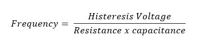
The equation to use is below - This is derived from capacitor charge equation.

What we need to calculate is what is the time constant to achieve a rise of up to 2v at 100ms when the source voltage is 5v?
From there we can pick a value for either R or C can calculate the other. The maths around this might look a bit hairy but easy enough to plug into a calculator. The equation to use is below - This is derived from capacitor charge equation.
Now we plug in out parameters
t = 100ms
Vs = 5v
Vc = 2v


Where
RC = the Resistor Capacitor time constant
t = time duration
Vs = Voltage source
Vc = Voltage over capacitor
ln = Natural Log function
putting that into the calculator we get an RC value of 0.196 (rounded off)
RC = 0.196
Now we can pick a value or either R or C. I'll pick a capacitor of 10uF
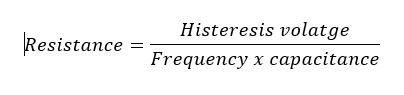
Rearrange the equation to solve for R


Which gives a resistor value of 19.6kOhm

2V at 100ms - spot on! The voltage over the capacitor and hence the reset line will be below 2v for the 1st 100ms which is more than enough to get the circuits to settle..
If you need to stick to the 3 or 6 clock cycles then just use the time in the equation above. For instance the time value for 6 clock cycles is 1.5mS.
RC = 0.0029
This time we can select a 1uF capacitor
which gives a resistor value of 2.9k Ohms
again - spot on.
A lot of examples for the RC values for the Z80 are
R = 10k
C = 47uF
which will hold the Reset low for just over 75ms which is way more than enough time for the processor and circuitry to settle down.

However, while this will work, there are two other aspects.
1. The voltage rise is not a sharp change and its always possible that as it passes the threshold between low and high it might not be as stable as you might think. this will be more of an issue the longer the time span is.
2. Its important, usually, to have a reset button and buttons add their own instability in due to very noisy contacts.
The answer to both of the above is the addition of a Schmitt trigger gate. This will provide a stable and sharp state change as well as debounce the button.
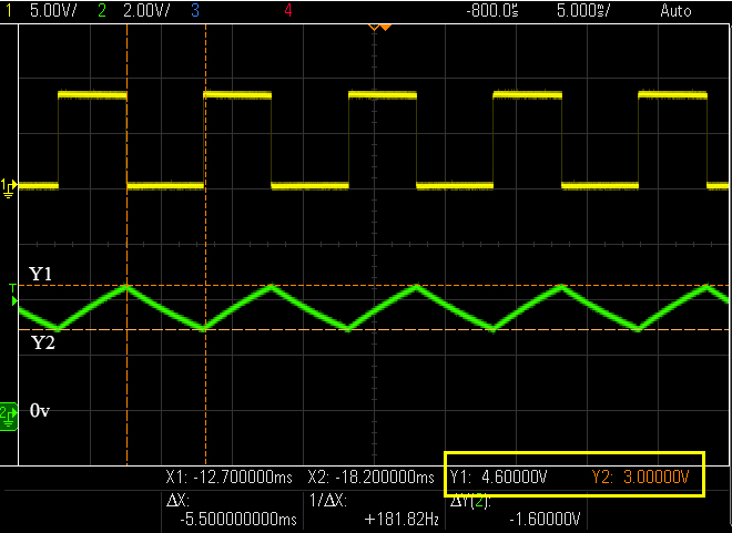
A Schmitt trigger includes some hysteresis which sets a window between two voltages, essentially latching the state while the signal is within the window.
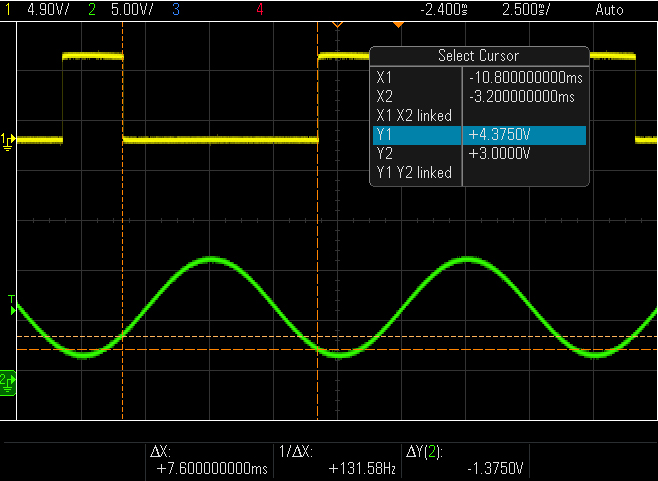
The Schmitt trigger will have an upper threshold and a lower threshold and its only when the signal passes through this threshold from the other threshold that the state will change. This ensure that any noise or instability is rooted out.
The graph below shows the that state only changes to LOW when the input voltage rises from below 2.7v to above it and then will only change to HIGH when the voltage passes 2.7v and goes though the lower threshold of 1.6V. This means that it does not mapper what happens between 1.6V and 2.7v, the state will not change and this makes the circuit much more stable.

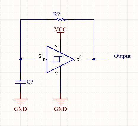
Generally a Schmitt Inverter is used for this, but will invert the state, so we need to add another one set it back again. This is also useful as then you have two reset signals, one HIGH one LOW which can then be used for different chips that have different Reset Active states.
The final circuit would look like this for a 100ms power on reset:
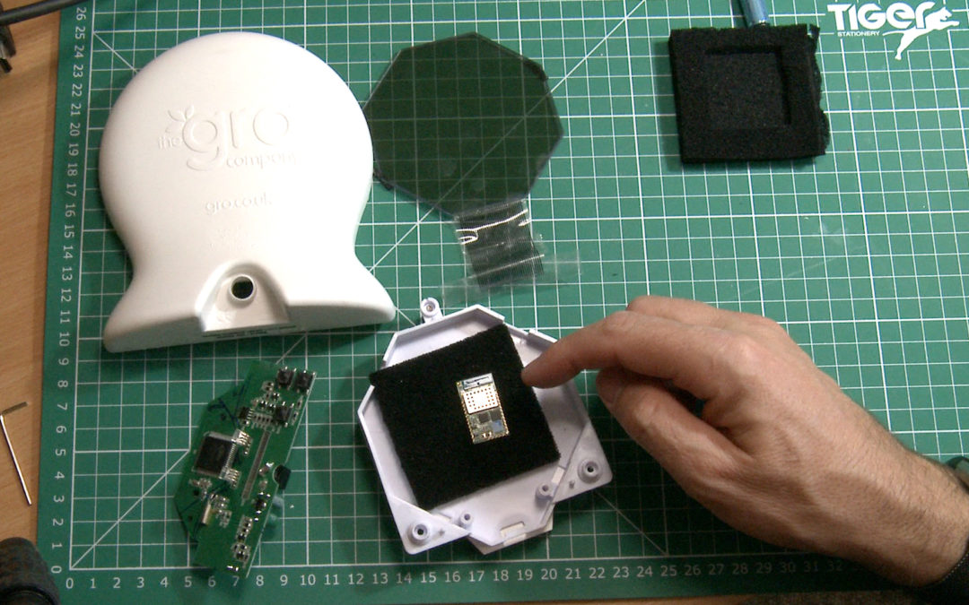
 e put together a breakout board for the clocks LCD. I needed 32 connectors for the flex ribbon to 2.54 pitch pins so that I can plug the LCD into a breadboard for testing and mapping out the LCD display. I have ordered the PCB from