The Schmitt Trigger Inverter oscillator is a very simple oscillator which can be useful but is also not very accurate or stable.
Pros
- Easy and simple circuit
- Easy timing calculation
- Useful for not critical oscillations or clock signal.
Cons
- Subject to frequency changes with temperature differences
- Subject to frequency changes with voltage supply differences – also influenced by the temperature
- Limited in frequency range on the higher level.
- Schmitt Trigger inverter was not designed for oscillation
Basic Principle
All oscillators are based on the same principle – a change in state between two voltages and a specified rate or frequency. Simple oscillators such as the Schmitt trigger oscillator use Resistor /Capacitor circuits for timing which is a simple and effective method. The resistor and capacitor size set the speed at which the capacitor is charged and discharged.
So what is a Schmitt trigger anyway?
“a Schmitt trigger is a comparator circuit with hysteresis implemented by applying positive feedback to the noninverting input of a comparator or differential amplifier. It is an active circuit which converts an analogue input signal to a digital output signal.” reference Wikipedia
The two key factors here are ‘Comparator‘ and ‘Hysteresis‘. The main point is that the inverter is setting two threshold points for comparison as thresholds for the ‘flip’ state. What this means is that between the two comparison points there is an area where a change in the signal does not affect the state of the output – this is Hysteresis – ie the stoic portion of the inverter. The Schmitt trigger symbol gives the clue – two lines representing the two thresholds with the single input and output.
The reason for the two thresholds is for stability. If you only have one trigger point you have a very real risk of misfires if there is noise in the signal. With the two thresholds for the upper and lower bounds, the area in between holds the state regardless of the noise. This is call hysteresis – sticking point.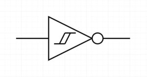
V+: Positive threshold (Min, Max and typical)
V-: Negative threshold (Min, Max and typical)
Vh: Histeroisis voltage (Min, Max and typical)
V+ is the voltage of the rising signal where the state will trigger
V- is the voltage of the falling edge where the state will trigger
Vh is the difference between the two.
This inverter is useful for converting a sine wave (or any changing wave) analogue signal to a square wave, also called a wave shaper.
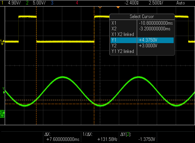
The waveform above shows the green sine wave (100Hz) input from a signal generator and the yellow is the inverted output. When the voltage of the sine wave rises above 4.3v the state of the inverter flips to 0v (inverted to the input of the positive rising input signal), the output does not change until the waveform drops below 3V. The difference in voltage between the two state changes is 1.3v which is the hysteresis voltage of this device.
The positive and negative values will be different for different devices (TTL vs CMOS for example) and different supply voltages.
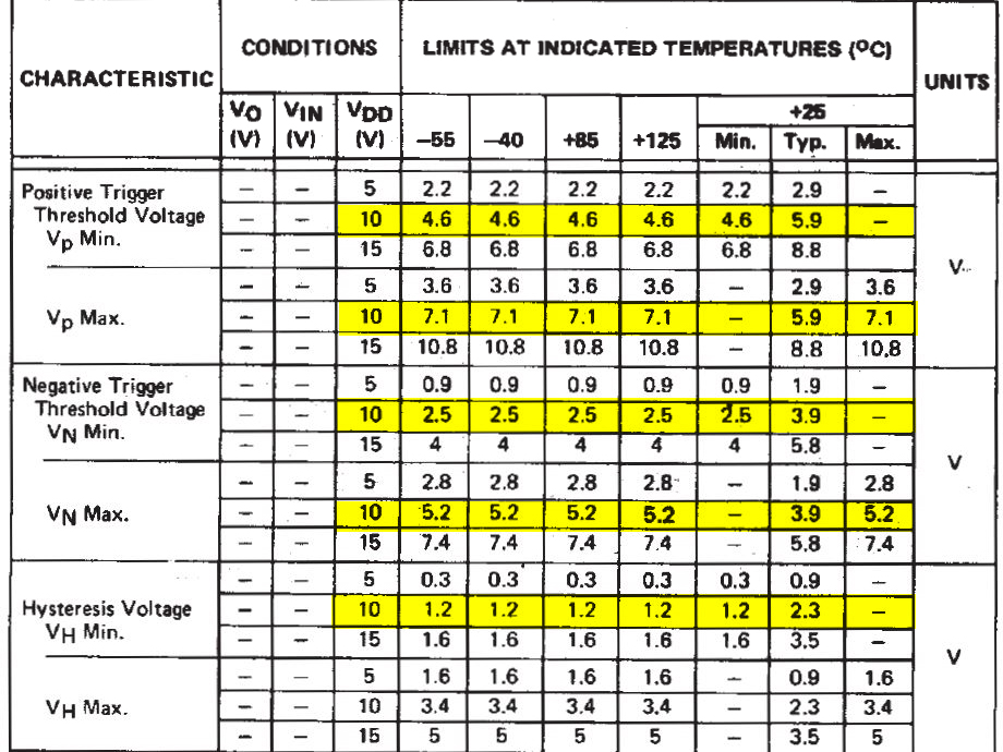
In the datasheet below for this device, highlighted in yellow for 10V, you can see the positive and negative thresholds. The right-hand columns show the typical values at 25 deg c. The values (Y1 and Y2) match up with the min column and the hysteresis ( difference between Y1 and Y2 ) value also fits into the min column. Voltages won’t be exact as the temperature is not the same (currently much less than 25Deg in my office as I write this!) and not every device is the same.
Note: As you can see from the temp and voltage columns, the threshold voltages vary considerably and this is the reason why this simple circuit is less than stable.
Ok, so how does this help make an Oscillator?
The hysteresis values are exactly what we need to create an oscillator. The upper and lower threshold values convert the input wave into a square wave by only triggering the inverter at the two different threshold points. What is needed now is an input signal that has feedback to keep the oscillation going and the way to do this is to set up delayed feedback from the output to the input of the inverter. We use an RC (resistor/capacitor) circuit to create timed feedback as follows.
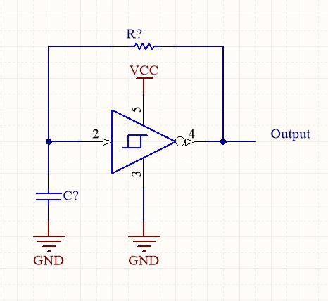
The way this circuit works is very simple.
When the power is applied, the input (pin 2) is low and therefore the output (pin 4) is high. (because this is an inverter). Current then flows from the output through the resistor and starts to charge the capacitor.
As the capacitor changes, the input voltage starts to rise. When it reached the positive edge threshold (in this case about 4.5 volts), the input is sufficiently high enough to change the input to ‘high’ and therefore the output to ‘low’.
Once the output is low the capacitor can discharge via the resistor, slowly lowering the input voltage at pin 2 until the voltage passes below the negative threshold voltage of about 3 volts where the inverter output flips back to ‘High’ and the process starts all over again creating a contained oscillator.
The magic is the two thresholds that allow for the state of the inverter to remain while the voltage is changing. If it were a single threshold, it would just generate a spike and not a clean square wave.
Setting the frequency
The frequency is a simple calculation, (you can get really complicated about it, but for the purposes of a simple circuit, a simple calculation will work) The trick, in this case, is to remember to use the hysteresis voltage for the calculation as its the distance between these two values there the RC timing takes place.
In other words the hysteresis voltage is a portion of the total voltage at the input pin as the voltages either side of the thresholds do not affect the state,
Remember that the larger the resistor or capacitor, the longer the capacitor takes to change and therefor setting either of these sets the charge/discharge timing.
Time = Resistor x Capacitance.
so the formula is :

The hysteresis voltage is included in the calculation because the charge and discharge of the capacitor happen between the positive and negative thresholds and so we use the difference between these values which is called the hysteresis voltage.
It’s usually better to choose the capacitor and then calculate the resistance needed as its easier to fine tune the resistance. The value is very unlikely to be an exact resistor value so you can then either create the correct resistance using serial and or parallel resistors or a potentiometer – this is much easier than trying with capacitors.
So we need to switch the formula around to calculate the resistance needed.
For this example I have chosen a 44nF ceramic capacitor.

Plugging in the values
Frequency = 100
capacitance = 44nF
Histereses Voltage = 1.3v
Giving a Resistor value of 295,545 ohms or closest value 300K ohm.
If you want a smaller resistor then choose a bigger capacitor value.
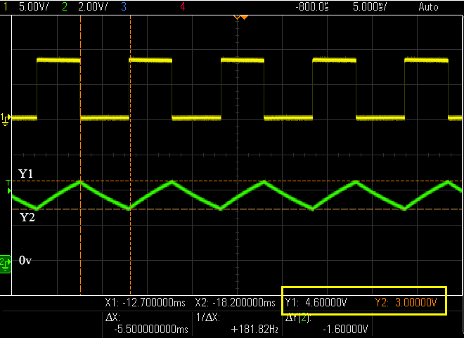
The oscilloscope capture above shows the green sawtooth wave that is generated by the resistor and capacitor circuit. As with the injected sign wave in the previous oscilloscope diagrams,.
You will notice that the triggering on the yellow square wave output is at the peak and trough of the sawtooth wave! This is the resultant wave caused when the inverter changes stage from High to Low. Looking at values Y1 and Y2 (in the yellow rectangle) you can see that they match the Positive and negative threshold values.
