
WHY POWER-ON RESET IS REQUIRED
Power-on instability is less of an issue with modern processors, but older or retro MPUs usually require a reset during startup. Many newer chips have this built in.
The reason is simple: the processor and the surrounding circuitry need time for voltages to stabilise. Components such as RAM and peripherals also need time to settle. If the processor starts too early, before everything is stable, it can crash immediately. At that point, you need a manual reset (if available) to recover. The RESET signal also reinitialises the processor and sets the program counter to 0x00, where the Z80 begins execution.
The fix is to hold the MPU in reset for a short time at startup—specifically, for a minimum number of clock cycles—then release it once the system is stable.
The Z80 manual specifies at least three full clock cycles of RESET on startup.
THE BASIC RC RESET CIRCUIT
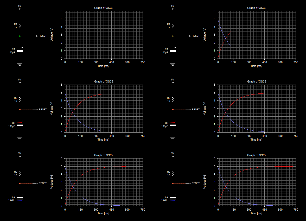
A typical solution is an RC delay circuit combined with a Schmitt trigger gate (usually an inverter). The RC network holds the RESET line low for a short period (in an active-low configuration), then allows it to rise high. For active-high reset systems, the logic is reversed. This method is commonly known as a “soft start”.
CALCULATING THE RESET DELAY
To know how long three clock cycles are, we can calculate that. Assume the Z80 is running at 4Mhz. That means each clock period is 250 ns.
The 3 clock cycles will be 250nS x 3 = 750nS. To be safe, we can double that to 6 clock cycles, which would be 1.5 µS (microseconds).
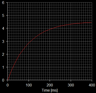
In reality, especially with a homebrew PC or something where start-up time isn't critical, the timing isn't that important as long as it's over 3 full clock cycles.
You can easily set a 100ms time just to be totally on the safe side.
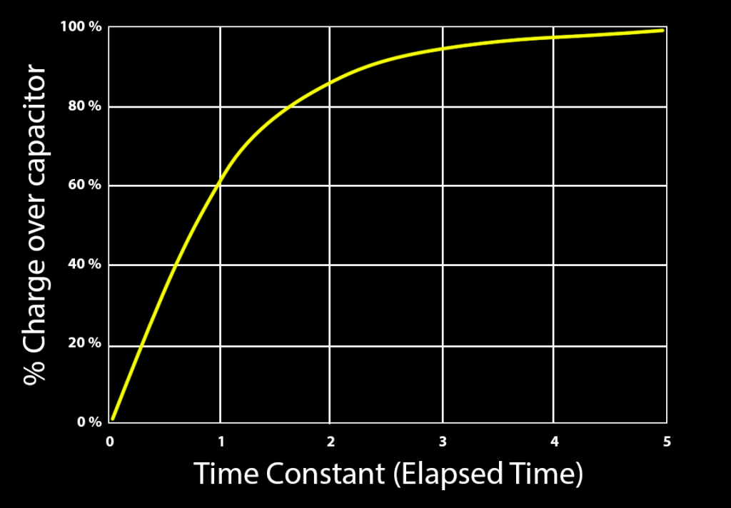
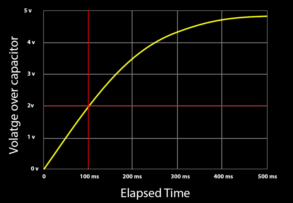
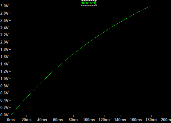
The main thing is to keep the Reset line below 2V for that duration. Let's work with a 100ms duration. Looking at the charge curve of a capacitor
CHOOSING PRACTICAL COMPONENT VALUES
The equation to use is below and is derived from the capacitor charge equation:
EQUATION
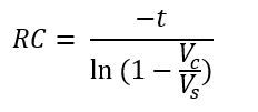
t = 100ms
Vs = 5v
Vc = 2v
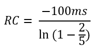
Putting that into the calculator, we get an RC value of 0.196 (rounded off)
RC = 0.196
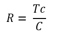
Now we can pick a value for either R or C. I'll pick a capacitor of 10uF
Rearrange the equation to solve for R:
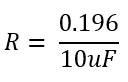
Which gives a resistor value of 19.6k Ω
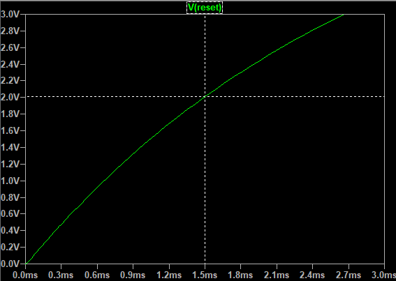
which gives a resistor value of 2.9K Ω
Again - spot on.
A lot of examples for the RC values for the Z80 are
R = 10k
C = 47uF
which will hold the Reset low for just over 75 ms, which is way more than enough time for the processor and circuitry to settle down.
IMPROVING RELIABILITY WITH A SCHMITT TRIGGER
However, while this will work, there are two other aspects.
1. The voltage rise is not a sharp change, and it's always possible that as it passes the threshold between low and high, it might not be as stable as you might think. This becomes more of an issue the longer the time span.
2. It's important, usually, to have a reset button, and buttons add their own instability due to very noisy contacts.
The answer to both of the above is adding a Schmitt trigger gate. This will provide a stable and sharp state change as well as debounce the button.
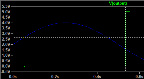
A Schmitt trigger includes hysteresis, which sets a window between two voltages and latches the state while the signal is within that window.
The Schmitt trigger has an upper threshold and a lower threshold, and the state changes only when the signal crosses one threshold from the other. This ensures that any noise or instability is rooted out.
The graph below shows that the state changes to LOW only when the input voltage rises from below 2.7V to above it, and it changes to HIGH only when the voltage passes 2.7V and then crosses the lower threshold of 1.6V. This means that what happens between 1.6V and 2.7V doesn't matter; the state will not change, which makes the circuit much more stable.
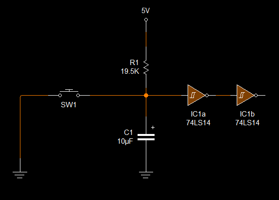
The final circuit would look like this for a 100 ms power-on reset:
0 Comments