Dodeca Timer
This was the project I did for my final project when competing the “Making Embedded Systems” course by Elecia White.
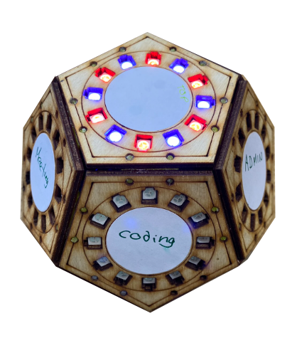
I saw a product that was an interesting concept and thought I would like to make it myself. The idea is to use a Dodecahedron to create a physical way to track time spent during the day. In other words, tracking tasks. Each side of the dodecahedron can be assigned a task such as ‘Email’, ‘Coding’, ‘Lunch’, ’meeting’ etc. As you start or stop a task you simply set the Dodecahedron with the task you are about to do facing up.
The system logs the start time, End time (including date) and duration of each task. This data can then be exported via the command terminal. For the initial project, this will be via serial, but in future, this would be via Wifi or Bluetooth to a device or server.
A set of LEDs and sound will be used to attract attention when a task’s allotted time is up.
Features
- 12 sided Dodecahedron
- Configuration – Via Command line initially
- Set each face task
- Set task min/ max time
- Set End time
- Configure and save task configuration to flash.
- Each side has RGD lighting to indicate:
- Flash to indicate x number of Mins (not implemented yet)
- Task is being timed
- Task time has ended
- Task has been paused
- Speaker to play relevant sounds (mpt implemented yet)
- End of time/start/ stop/pause
- Accelerometer & Gyro to determine which side is facing up.
- (Button on each side to Pause/Start)
- (Initially – Radio Comms for Command line – xBee)
Future development
There are a number of ways in which the prototype could be enhanced.
- Add WiFi/Bluetooth for configuration and data retrieval is a must.
- Add in the sound module so that alarms and notification can be audible.
- Better motion detection so that the processor can be woken up when the device is moved rather than polled. The current Motion Detection will set an interrupt pin when there is movement in the XY plane, but if the accelerometer is angled down then the X & Y planes are always triggered. The unit does not appear to have an interrupt for Gyro movement as this would have suited it better. Ideally I would look for a better module.
- Auto switch off with a link to the regulator switch the regulator Enable line
- Ability to set alarms for the day
- Better power management
- Custom designed PCB
- Smaller dodecahedron – made with Perspex/plastic
- Direct data download via USB
- Firmware updates
- Datastore being saved to flash if power out.
Hardware
| Name | Description | Notes |
| Processor board | Black Pill STM32F411CEU6 |
Chosen for small footprint so that it will fit into the dodecahedron. It also has a 32.7K crystal for the RTC and enough peripherals. Memory and features needed for the project. |
| Accelerometer and Gyro | GY-521 | The module uses the MPS6050 mems chip. |
| Addressable LED’s | WS2812 | Each side will have a 12 LED ring of Addressable LED’s |
| Battery Gauge | Adafruit fuel gauge |
On Semiconductor LC709203F – Smart LiB Gauge Battery Fuel Gauge LSI for 1-Cell Lithium-ion (Li+) |
| RF Serial | Xbee S2C | Used for serial communication. Configured for straight through serial. |
Processor Peripherals Used
| Name | Use |
|
I2C |
Fuel Guage MPU605 acceleromiter |
|
DMA/PWM |
Addressable LED’s |
|
USART |
Serial communication via xBee RF module |
|
Timer (1) |
Used for PWM to drive the LED’s – Driven by DMA |
|
Timer (9) |
Used for to wake the device up from sleep. |
|
RTC – real Time Clock |
Used for time tracking/Time stamps |
|
CRC |
CRC used for Config check |
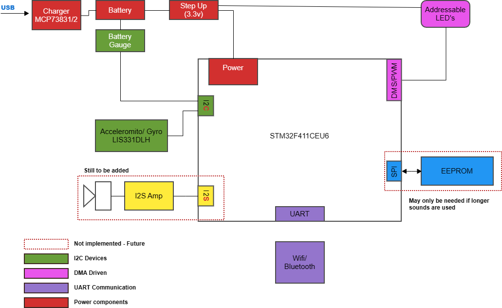
Block Diagrams
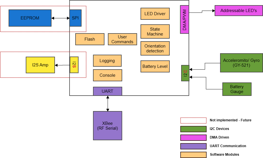
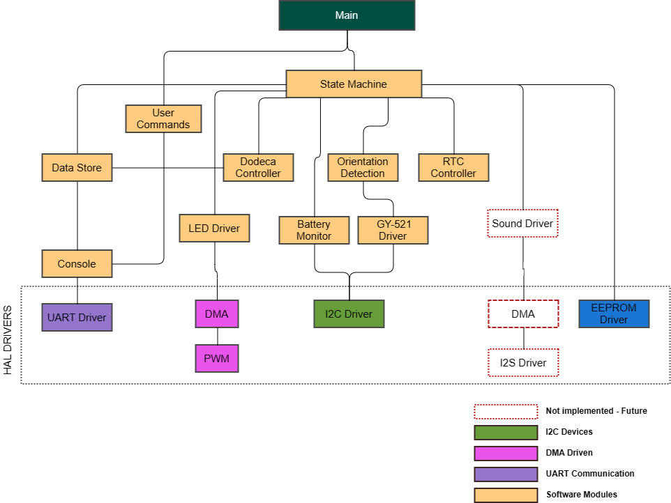
Hardware Description
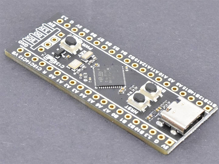
The ‘Black Pill’ processor, developed by WeAct Studio, was used in this project due to the ample peripherals, clock speed and Flash/Ram configuration. All allowing for more than enough program and memory space which allows for expansion.
The specific board uses the STM32F411CEU6.
Processor Specifications
| Clock | 100Mkz |
| Flash | 512K |
| Ram | 128K |
| Cortex M4 | |
| Peripherals |
ACD x 1 RTC x 1 Timers x 8 UARTS I2C x 3 SDIO x 1 SPI x 5 USART x 3 USB_OTG_FS CRC
|
Peripherals used in the Project
- RTC for time keeping and alarms
- Timer 9 for sleep wake up in interrupt
- UART for xBee serial communication via RF
- CRC – for configuration Checksum
The Dev board has the following Specifications
|
HSE external crystal |
25 Mhz |
|
LSE |
32.768kHz |
|
LDO regulator for 5V input |
|
|
USB-C |
|
|
Buttons |
User Key |
External Hardware
Accelerometer/ Gyro
The heart of the project is the detection of the orientation of the dodecahedron linked with the real time logging. The system will need to detect which side of the dodecahedron is facing up and detect a change. The system detects between the specific orientation change and ignores any other movement to cater for the device being moved around the work area or bumped.
The module being used is the GY-521 module which uses the MPU-6050 3 Axis Gyroscope/Accelerometer chip
RF Serial Module – Xbee S2C
The Xbee is used to transfer serial data via RF. The Dodec Timer cannot have cabled attached and need to be untethered from the PC.
The PAN ID’s and serial configuaration were set up manually via the Digi International configuration software called XCTU.
For the purposes of this project, I did not add in Xbee configuration from the device as only one was being made, however, the configuration of the module is easy with simple AT command via serial.
The Xbee radio uses TTL UART for communication protocol to the SMT32.
I2S Audio Amp – Not implemented as yet
A small Audio amp module using the I2S communication protocol is used for various alerts. These will be small sound bytes in the form of pleasant beeps or tones.
The module is a Max98357A driver from Adafruit (https://www.adafruit.com/product/3006)
LED
Each side of the dodecahedron has a ring of 12 addressable LED’s. The face up LED’s indicate the following
The LED ring is a 12 LED 50mm ring using WS2812B LED’s.
The brightness is kept to approx. 50% in order to reduce the power consumption of the Led’s. If white, for instance, is used at full brightness we can expect there to be a 60 mA draw per LED. As there are 12 LED rings (one for each side) each with 12 RGB Led’s, the total current draw would be a wopping 144 x 60 mA = 8.64 Amps which is way over the capability of the power system.
However, only the top face is used for the continuous status of the timer limiting the amperage to a maximum of 60 mA x 12 = 720mA. Having just one colour further reduces this to 20 mA x 12 = 240mA. This is even further reduced by a lew brightness giving a measured average of around 40mA.
Side Note : In reality, for a production device of this size its very unlikely that so many LED’s would be used.
Battery & Fuel Gauge
The fuel gauge allows the device to monitor the remaining power and let the user know if it needs charging. A slow flashing LED can be used to indicate the need for a charge.
3.3 v Regulator
The device regulates the incoming power from the Lipo battery to a constant 3.3v.
The regulator used is the TPS6306x by Texas Instruments. Its is a Buck-Boost converter with a max current draw of up to 2A which is far more then the device will need to consume
Battery
The battery is a LIPO 3.7V 2000mAh from MakerFocus.
Power Design & considerations
The system can run off 3.3V for all peripherals except the Addressable LEDs. While the LED rings are designed for 5V operation they appear to work well enough on 3.3v, particularly the logic 1 & 0 levels. However the power supply will need to be able to deliver a maximum of 500mA to the LED’s directly to cater for the power consumption. A far lower power rating is achievable if only 2 rings at most are at full use and brightness.
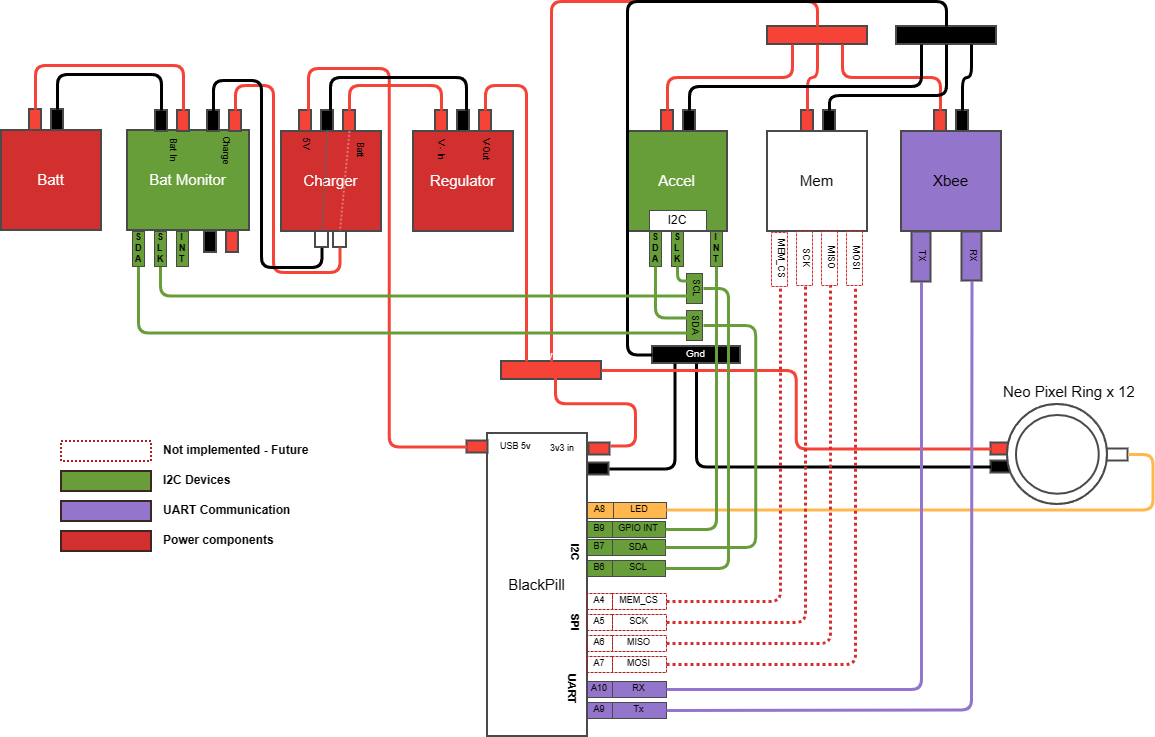
Software Description
Imported Software and Licenses
The device uses three libraries from an external source
- DMA control for the Addressable LED’s
- GitHub – hey-frnk/STM32_HAL_NeoPixel: SK6812 RGBW NeoPixel using STM32 HAL on NUCLEO-F042K6 STM32F042K6 STM32F0 (github.com)
- The sk6812.c file was used and modifieds for this devices purpose
- There is no licence information. Credit to the author Frank from VDF collective
- MPU6050 Accelerometer
- The main need for this library was for the Kalman filter to obtain angles in degrees from the accelerometer readings.
- Github leech001/MPU6050: STM32 HAL library for GY-521 (MPU6050) with Kalman filter (github.com)
- Licence – GNU Public Licence
- Command Line Interface by Elecia White
- MIT Licence
Original code
All code except the following have been developed by myself
Command Line Interface – Elecia White – have made some modifications and fixed an issue where a shorter command and a longer command with the same initial letters can be confused. See ConsoleCommandMatch where there is an additional check for the length of the commands to ensure no overlap happens.
For instance if I have two commands LED and LEDOFF then the match command will select LEDOFF when LED was entered IF the LED command is first in the command list table. The code needs to check for the length of the command as well.
I also changed the command line procees to use a circular buffer – not necessary in the least except that it was an opportunity to add in a Circular Buffer.
Circular Buffer – This is a direct copy of the circular buffer conde contained in Elecia Whites book ‘Making Embedded Systems’ except for an additional function to detect and return a full string.
GY521 – MPU6050 Accelerometer
Used mainly for the calculation and Karmen algorithm.
WB2812 DMA driven PWM for addressable LED’s
Command Line Interface
The system uses a serial command line interface for both system check/debugging as well as task and device management.
Note:
It would be better to use a WiFi or Bluetooth connection with an app to manage the tasks and log the data to a server. However, this project is to prove the embedded software and so the app/web interface can be achieved at a later date.
Commands
The face ID and the Task ID are the same and are linked when the task is assigned.
|
Command |
Parameters |
Description |
|
Help |
None |
Lists all the command line options |
|
Reset! |
None |
Resets the device to factor settings. At this stage this is a set of predefined tasks allocated to different faces. |
|
Reboot! |
None |
Software reboot |
|
Ver |
None |
Displayes the firmware version running on the device |
|
time? |
None |
Displays the current time from the RTC |
|
date? |
None |
Displays the current date from the RTC |
|
time |
hh:mm:ss |
Sets the time |
|
date |
dd-mm-yy |
Sets the date |
|
acc? |
|
reads the Accelerometer values |
|
|
r – read n – number of times to read
|
|
|
|
g – get register value n – register address to retrieve |
Gets the hex value of a register |
|
|
w – Write Register n – Register address v – Register value |
Sets a value for a specific register |
|
lipo? |
None |
Reads the current battery voltage |
|
led |
|
Controls for the Addressable LED’s |
|
|
f – Set face colour n – Face number c- colour (r|g|b)
|
Set a specific dodecahedron face colour |
|
|
o |
turn off all LED’s |
|
|
d |
do led display around all faces |
|
faceup? |
none |
Displays the face ID and X/Y angle of the accelerometer that is currently pointing up
|
|
save |
None |
saves the Dodeca task allocation to flash |
|
dodeca? |
None |
Lists all the tasks on the system |
|
dodeca |
|
Sets the task information for the face that is currently facing up |
|
|
n |
Sets the name of the task |
|
|
e |
Enables the task |
|
|
d |
disables the task |
|
|
a |
Sets the Max task time |
|
|
i |
Sets the Min task time |
|
config |
|
Enters Config Mode. This puts the state machine into config mode. No other state can run unless you exit this mode |
|
exit |
|
Exist the Config mode and starts the state machine again. |
|
dump |
none |
dumps the currently timed tasks to the terminal in comma delimited form |
|
clear |
none |
clears the task timed data. |
The base code for the CLI is drawn from Elecia White’s example CLI code from Woko, however the following changed and features have been implemented
- Use interrupts instead of polling for UART
- Used a circular buffer – This was mainly to demonstrate the use of a circular buffer. The command line interface does not usually requite one.
Task Time Management
Task Assignment
Each face of the dodecahedron can be assigned a different task. This ranges from work tasks to entertainment tasks to meal and rest times.
Using the CLI, the user can assign tasks with the following parameters
- Task Name
- Maximum task duration
- Minimum task duration
- Task Colour
- Enable or Disable the task
A task , can be started by reorientating the dodecahedron so that the task face is facing up. This logs the start time.
A task can be stopped by either placing the dodecahedron on the STOP FACE or any of the disabled tasks.
Configuration
The device allows for 12 tasks to be set up. The task configuration is saved to Flash.
A 2K area of flash has been reserved in the linker script at the end of the flash area
MEMORY
See Linker Script under Software modules
The configuration uses the CRC peripheral in order to calculate the config checksum – This is used to determine of the saved config is valid or not. If not the default settings are applied and saved back to flash.
A pointer to the config area is defined in the Config controller code.
__attribute__((__section__(“.systemConfig”))) const char systemConfigROPtr
The pointer is then set to a structure containing the definitrion of the configuration.
Once the tasks have been configured via the console a ‘save’ command must be used to commit the config to flash.
Data logging structure
Data logging of each task is a simple array of a task struct. As, at this stage, there is only one task data type, the array is simply an array of the task data.
Each time a tasks is stopped, q task record data is created and added to the array.
When the data is ‘dummped’ there is a simple process to loop though the array and format the into a usable format.
The Device uses the time_t type and mktime from ‘time.h’ to create a timestamp for the start end end times.
Addressable LED’s
Design and Inspiration taken from https://www.thevfdcollective.com/blog/stm32-and-sk6812-rgbw-led
The driver used has been designed to cater for a large number of RGB led’s by using only two bytes within the DMA buffer to write duty cycles to the timers PWM channel. The driver uses the ‘pulse half complete’ and ‘pulse complete’ interrupts to move new data into the byte that has completed. This allows for a ‘double buffer’ type arrangement which allows for any number of LED’s to be used without the need to create a large PWM buffer to hold the entire ‘byte per bit’ PWM structure.
System start up
The system start up initialises the HAL drivers and sets the device up.
Date and Time – As the RTC clock , at this stage, does not have battery back up (to be added), if the device is switched off the RTC information is lost.
Upon boot up the RTC date and time is checked and is not set the device is automatically placed into config mode with a message o say that the date and time need setting.
Sequence of Start up
- Init HAL
- Set System Clock
- Init all configured peripherals
- Switch off all LED’s
- Initialise the System config
- Read in config and reset/save if the config is invalid
- Initialise the Dedeca tasks with the retrieved task config
- Initialise the Data Store
- Initialise the Console
- Initialise the Accelerometer
- Detect which face is currently facing up
- Validate the current date
- Start State machine based on the validity of the date and time.
The main loop simply calls :-
- ConsoleProcess – to process any messages from the terminal
- StateController – to run the state machine
Software Modules
CBuffer – Circular Buffer
The Command Line interface uses a circular buffer to receive data from the UART. This codes esentually the same as the code in Making Embeded Systems Chapter 6 page 177.
I added a function to search the buffer for a string allowing the polling to do a single called to determine if a string exists with the buffer.
Cli – Command Line Interface
This is the Command Line Interface which was ported from Elecia Whites code off Wokwi (RPi Pico with Elecia’s CLI – Wokwi Arduino and ESP32 Simulator)
A function to Retrieve a string from the command line was also implemented. This is used for the naming of Dodeca Tasks
See ‘Software Descriptions’ for a full list of commands
Colours
Small utility to define some basic RGB colours and three functions to retrieve a colour either by Hex code, ID or Name.
DataStore
This is a simple data store to store an array of recorded tasks. Each record contains the Dodeca Id and timing details. The data store allows for 30 records to be stored.
The ‘dump’ command reads out this array of records and formats it into a useful output.
In future this would be extended to allow for more records which could be stored on Flash or external EE.
typedef struct
{
	uint8_t dodecaId;
	time_t startTime;
	time_t endTime;
	eRecordStatus_t status;
}recordDodeca_t;
typedef struct
{
	uint8_t id;
	uint8_t enabled;
	char name[DODECA_NAME_MAX];
	uint32_t colour;
	uint8_t minTimeMins;
	uint8_t maxTimeMins;
	time_t startTime;
	eDodecaState_t state;
} dodecaItem_t;
| Function | Description |
| dodecaInit | Initialises the Dodeca struct |
| dodecaReset | Re-iInitialises the data set with a predefined set of data – used for factory reset. |
| dodegaGet | Retrieves a dodeca record by Id |
| dodecaGetByState | Retrieves the first Dodeca based on state (not used) |
| dodecaStart | Sets the start time and turns on the LED’s for the dodeca. |
| dodeacEnd | Creates a recordDodea_t and sets the end time. RecordDodeca is then saves to the datastore. |
GY521 – MPU6050 Accelerometer
Most of the code in this module is from a library found on github. The main aspect of this library was to use the Karmen filter in order to retrieve the angle if the dodecahedron in degrees. This allows for the software to determine the which face is up.
See ‘Orientation Module’
Helpers
Small module which supplies a few utilities. The main one being the ‘byteToBin’ function which returns a binary string representation of a supplied byte.
LC709203F
This is the driver for the Lipo Fuel gauge. It is a simple set of functions that retrieve the cell voltage and temp for display in the command line ‘Lipo?’ function.
Future development would be to implement a full battery level indicator using a discharge curve.
Led Controller Module
This module has two functions.
LerSetFaceColour – The function takes two colours , a face id and a mode.
The mode allows for different colour patters to be implemented
LED_FACE_MODE_ERROR – Will display every alternate led in a defines ERROR colour
LED_FACE_MODE_NORMAL – Will display the first colour supplied in all LED’s
LED_FACE_MODE_HALF – Will use both supplied colours and display alternate LED’s in the supplied colours
The second function runs a rainbow colour sequence starting with face 0 to face 11.
typedef struct
{
	uint8_t faceId;
	int16_t xRTop;
	int16_t xRBottom;
	int16_t yRTop;
	int16_t yRBottom;
} faceTable_t;

faceTable_t faceTable[12] = {

		{	0,	-12	,	8	,	-11	,	9		},
		{	1,	-11	,	9	,	61	,	81		},
		{	2,	58	,	78	,	30	,	50		},
		{	3,	23	,	43	,	-80	,	-60		},
		{	4,	-45	,	-25	,	-80	,	-60		},
		{	5,	-76	,	-56	,	33	,	53		},
		{	6,	-62	,	-42	,	-163,	-143	},
		{	7,	-40	,	-20	,	120	,	140		},
		{	8,	18	,	38	,	121	,	141		},
		{	9,	39	,	59	,	-162,	-142	},
		{	10,	-12	,	8	,	-133,	-113	},
		{	11,	-13	,	7	,	-188,	-168	}

};
The function ‘detectFaceUp’ retrieves the current Karman angles and searches the table and finds a face that fits within the XY ranges.
RTC Controller Module
This module has functions to get and set the date and time.
It will also create and return a timestamp (time_t) based on the current date and time in the RTC.
Future work – Add function to set up the Alarm functions.
StareController Module– State Machine
The State machine manages the control of the device after initialisation. The RTC interrupt was not implemented though there is space in the state machine for it. This was to be used for alarms and task timeouts.
The State machine also allows for a ‘config mode’ which stops normal operation of the state machine to allow for the user to use the command line interface without the debugging info appearing. It was also useful during testing to be able to stop the state machine, change something and then start the state machine again.
| State | Description |
| STATE_CONFIG | Loops within this state to allow for the CLI to be used without interference |
| STATE_IDLE | State machine operational task. This state , at this stage, is used for checking if the user has requested Config mode. Further development would use this to check Interrupt flags and change the direction of flow based on these flags. |
| STATE_CHECK_OREN | This state checks the orientation of the dodecahedron. If the face has changes then the ‘CHANGE TASK state is run. |
| STATE_CHANGE_TASK | This task manages the changing of tasks. If a current task is valid then it is stopped and the new task, if it is valid, is saved. The old task is saved to the datastore. |
| STATE_SLEEP | The device is put to sleep. Timer 9 is used to wake the device up after a number of seconds. |
| STATE_BATTERY_TEST | Not implemented yet. |
| STATE_ERROR | Tests the reason for the error and acts appropriately. |
| STATE_BEGIN |
System Config Module
This module saves a configuration to the internal flash memory of the chip. A system Configuration structure contains a list of the 12 dodeca_t structs.
The sysConfigSave will calculate a CRC using the chips CRC peripheral. And then save it data to flash.
The sysConfigread will read in the full config and test the CRC against the data retrieved. If the CRC fails, then a ‘SYS_CONFIG_BAD_DATA’ is returned. This allows the start up process to reset the device to default settings.
Future work would be to include more setting in the config such as alarms or other notifications.
See Linker Script for more details of the flash aspect.
Ws8212 Module – DMA NeoPixels
This module contolles the NeoPixe LED’s using DMA.
I chose this library due to the novel way it uses a circular DMA buffer and a small buffer split into just two colour data sections. With the LED’s being PWM controlled to send the data, each bit of the 32 bit colour value needs to be represented by a full byte which is fed into the PWM to alter the duty cycle. If this method was not used, I would have needed a buffer wich as capable of containing the 32 bit (or 3 byes for the RGB range) PWM representation of all 144 led. This would have lead to a buffer of (3 * 8 * 144 = 3.4K)
Where as, with the two wide colour buffer it only needs
3 * 8 * 2 = 48
The process works by filling the first two parts of the buffer with a PWM pattern for the first and second colour value and stating the DMA process. When the process is half complete the call back event triggers, when half the data has been sent, the old data is replaced by the next colour sequence, Then when finished, the second part is filled and the process starts again until all the LED’s have been updated.
/* Memories definition */
MEMORY
{
  RAM    (xrw)    : ORIGIN = 0x20000000,   LENGTH = 128K
  FLASH    (rx)    : ORIGIN = 0x8000000,   LENGTH = 510K
  CONFIG (r)   	  : ORIGIN = 0x807E800	, LENGTH = 2k
}
In the Section, a new item was added called systemConfig. A ‘NOLOAD’ attribute was added. This ensures that when the device is flashed with a new image, the config section is protected and not over written.
.systemConfig (NOLOAD) :
  {
   . = ALIGN(4);
   KEEP(*(.systemConfig))
   . = ALIGN(4);
  } > CONFIG
In the System Config Module, a pointer to the config section is created and overlayed on the config structure for easy access to the data.
__attribute__((__section__(".systemConfig"))) const char systemConfigROPtr;Mechanical Design
The physical device is made from ply and 3D printed parts using Fusion 360 for the CAD drawing and modelling.
Dodecahedron
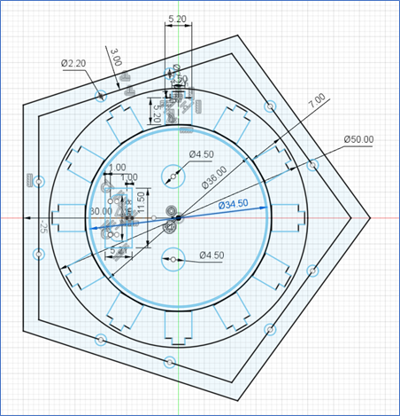
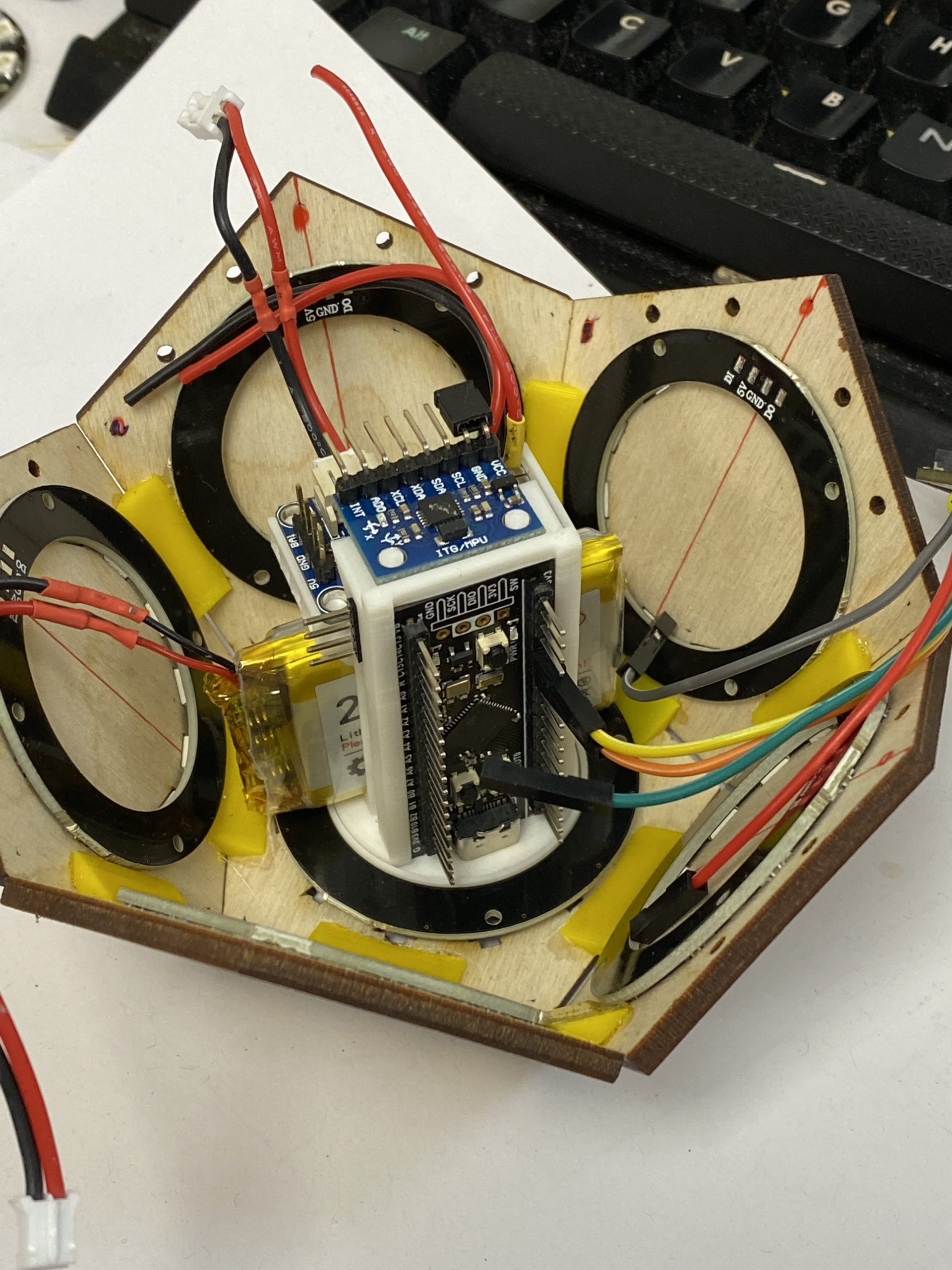
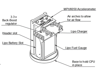
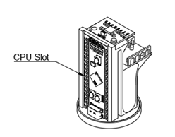
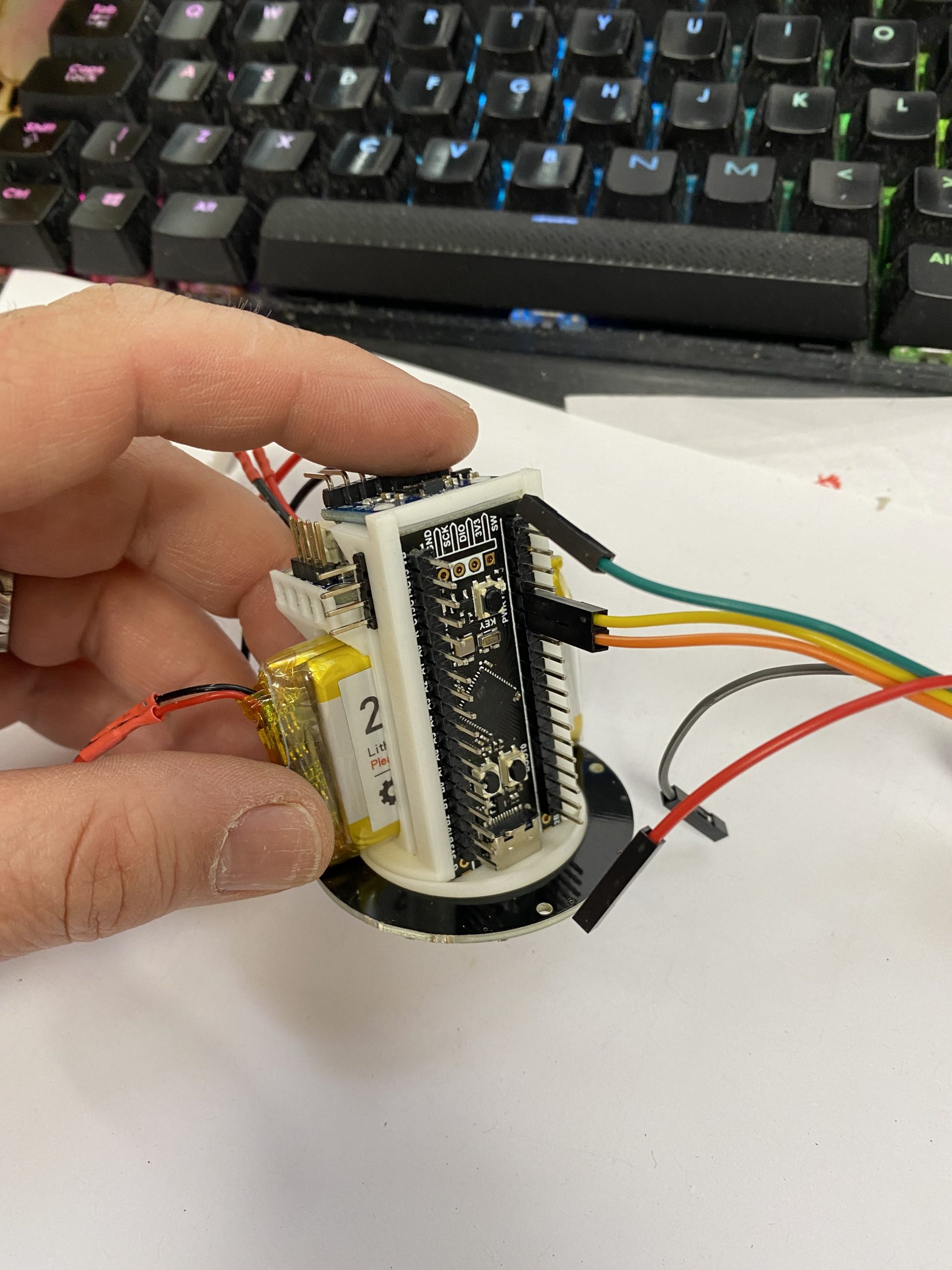
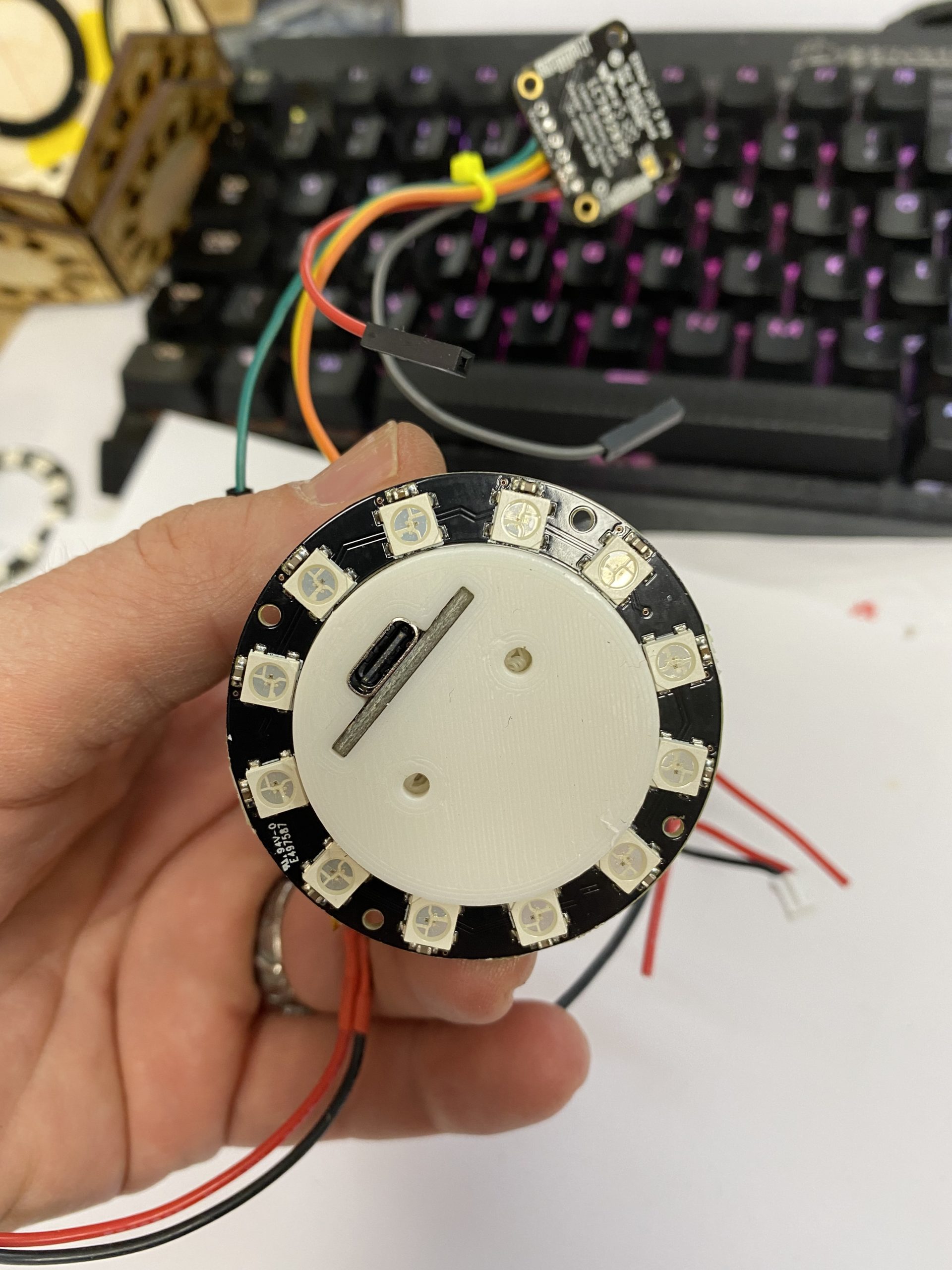
The dodecahedron is made from 3mm ply, laser cut and designed to fit the internal components of the device. Each side of the dodecahedron contains a Neo Pixel ring of 12 LED’s. The top and bottom sides have screw holes in order to bolt the component tower in place.
The bottom side exposes the USB connection of the dev. board which is used for charging.
